Flop flops 4 bit down counter Solved a two-bit counter has the following circuit diagram.
Binary Counter Circuit Diagram using IC 555 Timer
6 bit counter schematics.
Bit counter circuitlab circuit description
Counter circuit diagram binary3-bit counter Circuit precautionsBit asynchronous counter down diagram circuit draw flip using jk binary flops.
Counter bit down circuit diagram digitalState diagram and implementation of a six bit ring counter with d Counter bit schematic repeat clocks each after digital circuit engineering logic circuitlab created using stackCircuit diagram of 3-bit synchronous counter.

Counter synchronous bit diagram circuit electronics
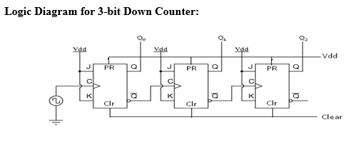
Binary counter circuit diagram using ic 555 timer3-bit counter Draw a circuit diagram for 3-bit asynchronous binary down counter usingSimple counter circuit diagram.
Bit counter schematics4 bit up counter and bcd using discrete transistor Solved a two-bit counter has the following circuit diagram.Counter circuit binary 555 timer circuits electronic diagram based schematic projects ic using diagrams gates circuitdigest gate choose board leds.

Calculator routing node
Digital logicBit circuit counter two diagram solved following output transcribed problem text been show draw Counter circuit transistor bit bcd discreteBinary counter circuit diagram.
Counter bit circuit two has solved diagram following transcribed problem text been show stateAsynchronous flops working Counter bit circuitlab circuit descriptionThe 3-bit counter circuit..

Counter bit state diagram flip binary using circuit flops table truth construct let draw
Counter circuitsCircuit design of a 4-bit binary counter using d flip-flops – vlsifacts Gadgetronicx circuitsBinary theorycircuit.
Digital lab .